
NIST IETF Backed Network Redundancy Design for EngineersDesign to eliminate single points of failure in proportion to business impact, not uniformly across every system. The core patterns are disjoint dual-homing, N+1 or N-2 capacity sizing, fast failure detection paired with routing-level fast reroute, duplicated dependent services like DNS and DHCP, and a verification plan that tests failures before production does. A business-impact analysis should decide how far each site or system goes.
TL;DR:
- Redundant paths should be physically disjoint and verified through thorough inventory and Shared Risk Link Group mapping to avoid hidden shared failure points.
- Dual-homing, load balancing, and multiple availability zones are essential at every layer to ensure resilience against failures in links, devices, power, and services.
- Capacity sizing must account for business-impact risks, with N+1 chosen for single faults and N-2 for systems where multiple simultaneous failures are possible, based on recovery objectives.
- Fast failure detection using protocols like BFD and routing protections such as LFA or MRT require careful tuning and testing under production-like traffic to prevent false failovers.
- Managed service providers can simplify maintenance by performing ongoing testing, SRLG verification, and operational document management, especially for complex or high-impact redundant networks.
Table of Contents
- Core design principles and when to apply them
- Inventory failure domains and map dependencies
- Redundancy techniques by layer: link, device, power, and service
- Capacity and resilience sizing: N, N+1, and N-2
- Fast detection and routing-level protection
- Testing, simulation, and verification plan
- Documentation, runbooks, and operations playbooks
- Practitioner proof: runbooks and operational lessons
- Author perspective: tradeoffs and when managed services make sense
- California Telecom as an option for managed redundant networks
- Sources
- FAQ
Core design principles and when to apply them
Redundancy design starts before any topology decision gets made. NIST's contingency planning guidance recommends building a business-impact analysis first, then setting recovery time and recovery point objectives for each service, because high-impact systems justify fully redundant solutions like alternate sites and real-time mirroring while lower-impact systems can run on cheaper contingency options. Skipping this step is how engineers end up over-building a file server and under-building a payment gateway.
Once impact and recovery targets are set, a handful of principles govern every design choice that follows.
- Disjointness: redundant paths must not share physical or logical failure points, not just appear separate on a diagram.
- Vendor and carrier diversity: a second circuit from the same carrier through the same point of presence is not real redundancy.
- Independent power and physical paths: separate conduits, panels, and where possible separate entry points into a building.
- Testability: a redundant path that has never been forced to carry traffic is unverified, not redundant.
- Observability: you cannot fail over to a path you cannot see the health of in real time.
The tradeoff is operational complexity. Every redundant path, duplicate service, and failover mechanism adds something that has to be monitored, patched, and tested on a schedule. Centralizing redundancy at a regional hub lowers cost and complexity but concentrates risk; distributing it to every site raises resilience but multiplies the number of things that can drift out of configuration.
Pro Tip: Centralize redundancy for low-impact, cost-sensitive sites and distribute it for sites tied directly to revenue or safety, rather than applying one redundancy template everywhere.
Inventory failure domains and map dependencies
A design built on disjoint paths still fails if the paths share a hidden common point. The fix is a failure domain inventory before anything gets deployed.

Items to inventory include physical NICs, top-of-rack switches, rack-level PDUs, building conduits, carrier points of presence, autonomous system and provider overlaps between "redundant" circuits, cloud availability zones, and service-layer dependencies like DNS, DHCP, and authentication. A shared regional outage at a DNS provider or an identity service can take down two physically redundant data centers at once just as easily as a cut conduit.
The output is a Shared Risk Link Group (SRLG) map: a table listing each link or device alongside every other link or device it shares a physical or logical dependency with. A usable template records, per segment, the circuit ID, the conduit or duct ID, and the physical termination location at each end.
- Pull circuit IDs and demarcation points from every carrier contract for sites you believe are dual-homed.
- Request as-built conduit and duct routing from the carrier or building owner, not just the logical path diagram.
- Identify the physical termination location (POP or hut) for each path and flag any that converge.
- Cross-reference cloud zone IDs and ASN assignments for any service with a cloud component.
- Record the findings in the SRLG map and revisit it whenever a circuit, provider, or cloud region changes.
Redundancy techniques by layer: link, device, power, and service
Redundancy has to be engineered at every layer independently, because a failure at one layer rarely trips protection at another.

At the edge, disjoint dual-homing means two circuits that do not share a conduit, a PON split, or a carrier point of presence. Academic modeling of dual-homed access networks found that a physically and logically disjoint alternate path can provide full protection against a single link failure, while a path that shares even one segment loses most of that protection. Carrier diversity means verifying the underlying fiber route, not just the invoice issuer.
Inside the LAN, link aggregation and multi-chassis link aggregation (MLAG or vPC depending on vendor) let two physical switches act as one logical device for a server's dual-homed NICs, avoiding the slower convergence of Spanning Tree alone. First-hop redundancy protocols, HSRP, VRRP, and GLBP, give hosts a stable default gateway across two or more routers: HSRP and VRRP provide active/standby failover, while GLBP adds load balancing across multiple gateways.
Across the WAN, SD-WAN active-active configurations use two or more carrier circuits simultaneously rather than holding one in standby, with 4G or 5G as a last-resort failover path for sites where a second wired circuit is not practical.
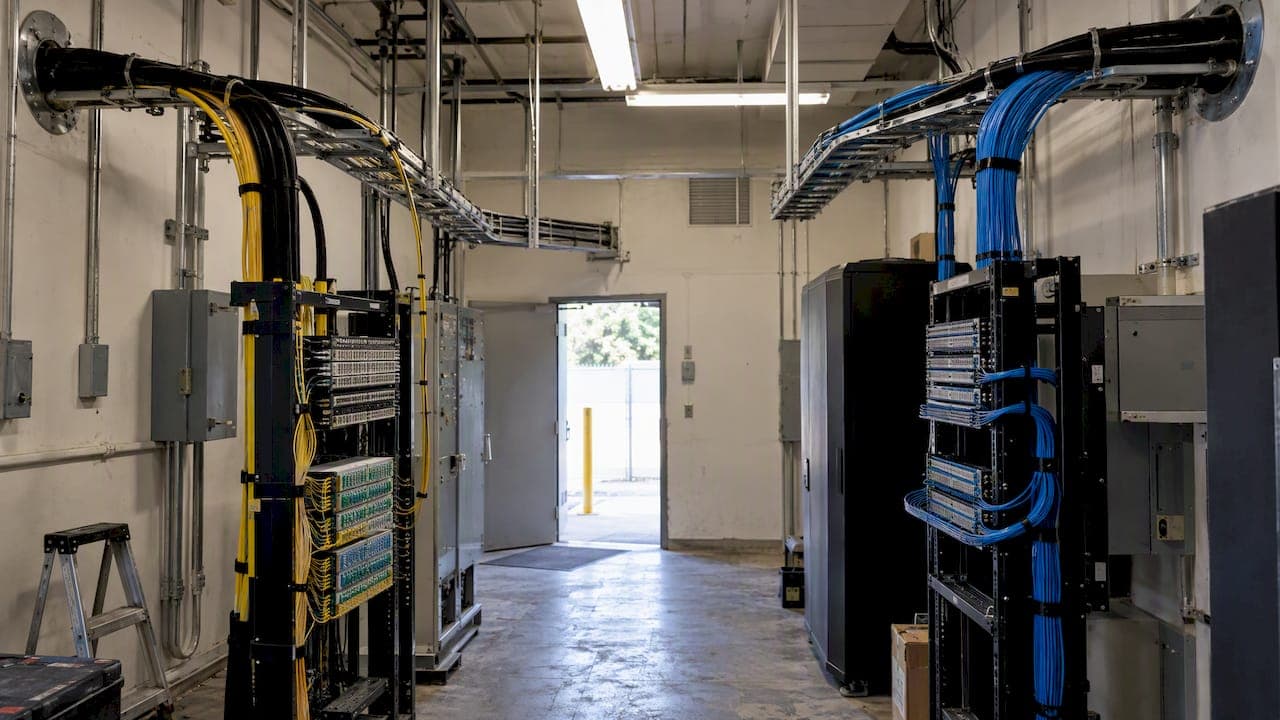
Power and physical redundancy follow the same disjointness rule: dual PDUs per rack, UPS and generator feeds on separate electrical panels, and an A/B power policy where every dual-corded device draws from both feeds.
At the service layer, DNS and DHCP should run hot-hot across two independent hosts, cloud workloads should span multiple availability zones, and virtual machines should use NIC teaming at the hypervisor so a single physical adapter failure does not take the VM offline. NIST SP 800-125B recommends exactly this pattern: duplicate DNS, duplicate DHCP, and multiple availability zones so a service dependency never becomes the single point of failure the rest of the design was built to avoid.
Pro Tip: Test FHRP failover and SD-WAN path switching under real traffic load, not an idle lab link, since convergence behavior under load is where most failover designs break first.
Capacity and resilience sizing: N, N+1, and N-2
N is the baseline capacity a system needs to run normally. N+1 adds one spare unit beyond that baseline, enough to absorb a single failure. N-2 describes a design that keeps running after any two independent failures, common in facilities or core links where a second simultaneous fault is a realistic risk. An "N-1 test" removes one unit and confirms the remaining capacity still meets demand; an "N-2 test" removes two and confirms the same.
Mapping a redundancy level to business impact starts with the recovery targets set during the business-impact analysis: a service with a near-zero recovery time objective justifies N-2 sizing and active-active paths, while a service tolerant of an hour of downtime may only need N+1.
- A link sized at 100 Mbps of expected peak traffic running at N+1 should carry two paths each capable of handling the full 100 Mbps, not 50 Mbps each, or the surviving path saturates the moment the other fails.
- Compute clusters need the same headroom logic: if losing one node must not degrade service, the cluster needs at least one full node of spare capacity beyond peak load.
- VM NIC teaming and hypervisor-level failover should be configured to reroute automatically without manual intervention, since a manual step during an outage is itself a point of failure.
NIST's contingency planning guidance ties redundancy level directly to business impact, advising that fully redundant, higher-cost options like mirrored alternate sites are reserved for the systems where downtime cost justifies the spend.
Fast detection and routing-level protection
Fast failover depends on how quickly a failure is detected and how predictably the network reroutes around it. Bidirectional Forwarding Detection (BFD) is the standard tool for sub-second failure detection, running in either asynchronous mode, where both ends send periodic control packets, or demand mode, where detection is triggered on request. RFC 5883 warns that aggressive BFD timers must be provisioned carefully, since interface, link, or CPU congestion can trigger false failovers that are worse than the outage they were meant to prevent. RFC 8562 extends this caution to multipoint BFD, recommending session limits, authentication, and congestion-aware provisioning to avoid runaway sessions.
For routing-level fast reroute, Loop-Free Alternate (LFA) is the simplest option but its coverage is topology-dependent: RFC 7490 on remote LFA makes clear that engineers need to calculate actual repair coverage for their topology rather than assume enabling the feature protects every link. Maximally Redundant Trees (MRT), described in the MRT-FRR architecture draft, can deliver complete coverage but requires consistent router capabilities across the whole protected area, which raises the operational bar.
A few practices reduce surprises during failover:
- Configure OSPF or BGP graceful restart and non-stop forwarding so a control-plane restart does not trigger unnecessary reconvergence.
- Tune hold timers conservatively enough to avoid route flapping during brief link blips.
- Apply prefix filtering and Route Origin Authorization through RPKI for internet-facing routes.
NIST's 2025 draft guidance on routing security recommends RPKI, ROA-based origin validation, prefix filtering, and source-address validation as controls that harden internet-facing routes against hijacking, which is as much a resilience issue as a security one.
Pro Tip: Validate BFD timers against production-like traffic and CPU load before trusting them in a live cutover, since lab conditions rarely reproduce the congestion that causes false positives.
Testing, simulation, and verification plan
A redundancy design is a hypothesis until it has been broken on purpose. NIST research on resilience testing recommends systematic scenario generation that covers correlated failures, not just single-component tests, because real outages rarely respect the assumption that only one thing breaks at a time.
- Build a test matrix covering single-component failures: one link, one switch, one power feed.
- Add correlated-failure scenarios: power loss plus carrier outage, or dual-node failure against a shared core switch.
- Run BFD and FRR tests under production-like load, not idle traffic, to surface false positives before they happen live.
- Capture packet loss, convergence time, and application-level recovery for each test.
- Define pass and fail thresholds against the recovery time and recovery point objectives set earlier.
- Automate the test suite where possible and log every run for regression comparison.
| Test type | What it validates | Pass criteria example |
|---|---|---|
| Single-link failure | Path disjointness, FRR coverage | No packet loss beyond sub-second convergence window |
| Correlated power and carrier failure | Shared failure domain exposure | Service stays within recovery time objective |
| BFD under load | False-positive risk at production traffic levels | No failover triggered without actual link loss |
| Service dependency failure | DNS/DHCP/auth redundancy | Secondary service answers within defined timeout |
Documentation, runbooks, and operations playbooks
A redundant design only helps during an incident if whoever is on call can execute the failover without guessing. The minimum runbook contents: the dependency map, the SRLG map, the exact verification commands for confirming a failover succeeded, the rollback steps, and an escalation tree naming the service owner for each system.
- Keep a test date, an owner, and a change log on every runbook so stale documentation gets caught before an incident, not during one.
- Link each runbook step to the monitoring alert that would trigger it, so the on-call engineer moves from alert to action without searching.
- Include a staged failover sequence rather than an all-at-once script, since triggering every redundant path simultaneously can cause a cascading overload on whatever capacity is left standing.
- Build a short post-failover checklist: confirm traffic on the new path, confirm the failed path is isolated, confirm alerting has cleared, and confirm no secondary service (DNS, DHCP, authentication) is still pointed at the failed resource.
Pro Tip: Store runbook verification commands next to the monitoring dashboard that triggers the alert, not in a separate wiki, so the on-call engineer never loses time switching tools mid-incident.
Practitioner proof: runbooks and operational lessons
A managed services provider designs and deploys multi-site redundancy using its own engineers rather than handing a circuit order to a carrier and hoping the topology holds. Sourcing connectivity from multiple carriers matters directly for the dual-homing and diversity principles above: a provider that can choose among many carriers can actually verify disjoint physical paths instead of defaulting to whichever circuit is easiest to sell.
Runbooks for firewall high availability, SIP trunk failover, and redundant internet setups follow the same structure outlined above: dependency map, verification commands, rollback steps, and an escalation tree. A worked example for firewall high availability walks through the verification commands an engineer runs immediately after a failover, and a companion piece on setting up redundant internet covers the dual-homing decisions a site-level design has to make.
Author perspective: tradeoffs and when managed services make sense
Running true redundancy in-house means staffing for carrier coordination, SRLG verification, and failover testing on a recurring schedule, not just at launch. That operational load is where most in-house designs quietly degrade: the test calendar slips, the runbook goes stale, and nobody notices until the day a failure doesn't fail over cleanly.
A managed provider earns its place when the coordination cost across carriers and sites exceeds what an internal team can sustain. The tradeoff is real: you give up some direct control in exchange for an SLA and a team whose job is keeping the redundancy current. A fair way to decide: if nobody owns the SRLG map and the last failover test predates the last org chart change, the in-house model needs help.
— Jim
California Telecom as an option for managed redundant networksIf the inventory and testing steps above surface more gaps than your team has time to close, that is a design and operations problem a managed service provider can address. Managed SD-WAN gives multi-site businesses active-active path control across carriers instead of a single circuit with a cold-standby backup, dedicated fiber internet covers the sites where a carrier-grade primary link is non-negotiable, and network monitoring provides a dashboard for the observability that every layer of this guide depends on.
The starting point is a free consultation where our engineers map your SRLGs and produce a redundancy gap analysis against your actual topology, not a generic checklist. Get a free consultation to find out where your current design still has a hidden shared failure point.
Sources
- Survivability problem in hierarchical wireless access networks with dual-homed end users
- RFC 5883 — BFD guidance for multihop/multipoint use
- NIST Special Publication 800-34 Rev. 1: Contingency Planning Guide for Information Technology Systems
- RFC 8562 — BFD for Multipoint Networks
FAQ
What are the three types of redundancy?
Network engineering commonly groups redundancy into hardware redundancy (duplicate devices like switches or routers), path redundancy (disjoint physical and logical links), and service redundancy (duplicate dependent services such as DNS or DHCP). Each type protects against a different failure domain, so a complete design uses all three rather than relying on one.
What is redundancy in design and how is it used?
Redundancy in network design means building duplicate capacity, paths, or services so a single failure does not interrupt the service the network supports. NIST's contingency planning guidance frames its use around business impact: engineers size redundancy to match what an outage would cost, rather than maximizing it everywhere.
What is N-1 and N-2 redundancy?
N-1 and N-2 refer to how many independent failures a system can absorb while still meeting demand. An N-1 design and test confirms the system survives one failed component, while an N-2 design and test confirms it survives two simultaneous failures, a standard used for critical links and facilities where a second fault during repair of the first is a realistic risk.
Which network topology is the most redundant?
A full-mesh topology, where every node connects directly to every other node, offers the most redundant paths of the common topologies, since the loss of any single link still leaves a direct path between most node pairs. In practice, cost and complexity usually push designs toward a partial mesh or hub-and-spoke model with dual-homed access, which recovers most of the resilience benefit at a lower cost.
How does redundancy affect network performance and latency?
Active-active redundancy, where traffic runs across multiple paths simultaneously, can improve performance by spreading load, while active-standby redundancy adds no latency in normal operation but introduces a brief convergence delay during failover. The actual delay depends on detection method: BFD-based detection typically converges in well under a second when timers are tuned and validated under load, as IETF guidance recommends.